Some simply buy, for others this implies self sufficiency, but we will all get there!
Disclaimer
Tube amplifiers operate with high DC voltage, mortal danger is present within millimeters, this could be a good reason to stay clear if you are inexperienced.
Even disconnected capacitors can take considerable time to fully discharge.
Motivation comes from having experienced very good audio; once heard it cannot be unheard, from then on, when hearing poor sound the new standards that have been set will not step aside.
Gratis workshop
Index
Amplifier technology by Bert van der Kerk
The amplifier website from Bert van der Kerk relates his voyage through the Williamson way of DIY, which during a period in the fifties of previous century, was a hole in the wall for early adopters.
It is proof that, if you own a pair of the extra ordinary output transformers, and if you know how to operate in the mortally dangerous world of high voltage, it still is possible in our times to relive the spine chilling experience of good sound.
Chapter 1. Introduction.
Chapter 2. The History
Chapter 3. The Circuit
Chapter 4. The Tubes
Chapter 5. The Personal Story
Chapter 6. Project with Unitran Transformers
Chapter 7. First BvdK transformer amp, case design by Pascal Jansen
Chapter 8. The UltraFine Output Transformer Project
Chapter 9. The Power Supply, The Time Delay Power Switch
Chapter 10. Putting into Operation, Adjusting Bias
Chapter 11. Applying Negative Feedback, Adjusting C10, R26P
Analogue replay ERA heritage from France
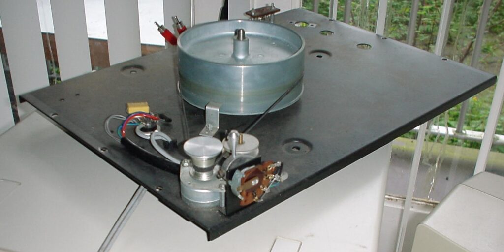
Le site ERA reprend l’histoire de cette marque à l’esthétique des années 60, tentant de retracer une partie de son histoire, d’évaluer ses mérites qualitatifs et de documenter sa mécanique. En plus, il y a la l’histoire personnelle de cette base magnifique qu’est la platine ERA 444 pour toute expérimentation électromécanique, menant, en passant par les tentatives de resoudre plusieurs problemes, a la conception du bras au palier a multiples pointes seches.
Chapitre 12. La génération Mk3 jusqu’à 6066, soupçons
Chapitre 13. La modularité et ses pièces
Chapitre 14 mise en garde
Chapitre 15 La poulie 33/45 tours
Chapitre 16 les contacts et le cablage
Chapitre 17 La geométrie d’un bras 9 pouces
Chapitre 18 les bras à pointes sèches
Loudspeakers
Die Lautsprecher Webpage versucht klar zu machen wie es moglich ist um, ohne viel Geld, das Besitz zu erwerfen von das immer teuersten Teil eines Hifi Ketten.
Die monatliche spendiering um Hobby hifi und Klang&Ton zu lesen, gesamt die Preis ein Paar guten lautspecher erreichend, hat bei mir die Wissenschaft aufgebaut um die, fur mich richtigen, Wahl zu machen:
Kapitel 19. Einzellautsprecher System mit Tieftonlabyrinth.
Kapitel 20. Einpunktwiedergabe
Kapitel 21. Lautsprecher aus Wellpappe
Listening environment & Musical taste
Het moeilijkste als laatste: welke keuzen te maken, om binnen de eigen mogelijkheden, niet per se het maximaal mogelijke, maar in ieder geval een bevredigend resultaat te bereiken.
Het vergaren van informatie is hierbij net zo belangrijk als het bereiken van de mentale staat nodig voor het ontwijken van dwaalwegen. Het doel is uiteindelijk naar muziek luisteren.
Hoofdstuk 22. de luisterruimte
This also applies to the ERA turntables, Allways unplug it from the AC mains : the power/speed commutator switch has open contacts that can easily, unvoluntarily, be touched. There is a high risc of the contacts touching the steel hull body, during the particularly difficult manipulation of opening the case. Unplug from the AC mains!
This is a mutilingual website written in the language of primary interest for each subject, if the page is auto translated, please be aware of the inaccuracies and possible contradictions of AI technology: double check all that is crucial, or seems improbable!
Wherever possible bold affirmations will be expressed as prudent hypothetical thought, all remaining blatancy has to be considered as pending to be re-written.
most text will be 3 stage: quick read, argumentation and elaboration of the relative importance, and ease of realisation
Introduction
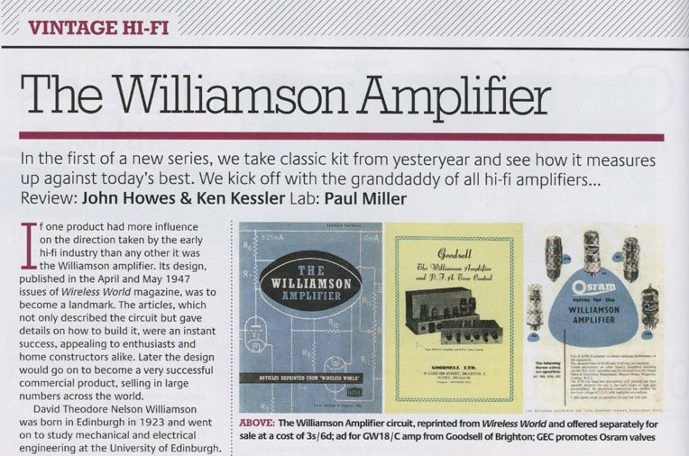
An article in the British magazine HiFi News in January 2010 by John Howes and Ken Kessler remembered the 63rd anniversary of the Williamson amplifier with a listening competition of an original Williamson “mono-block” amplifier against some modern High End amplifiers and a lab comparison of its specifications which it both won. The final conclusion: “Why is no one making these amps?”.
Indeed, the author made some of these amplifiers, some with existing ouptput transformers and some with output transformers he developed himself and every dag he enjoys his favorite music through those amps.
The image below shows the headline of the article.
This website will examine the possibility of creating such amplifiers with the products that are still available today and will try to give solutions to questions that will rise.
This website is meant for those people who have experience with servicing vacuum tube amplifiers, who are familiar with Ohm’s law and are aware of the dangers of the high voltages in these devices and the risk that these high voltages remain in these devices even when they are switched off.
If you don’t have this experience and knowledge buy some books with theory on this subject and start with a simple tube amplifier kit.
Introduction
The Williamson amplifier is a design by the British engineer D. T. N. Williamson and was first published in the spring off 1947 in “Wireless World”. Williamson was employed by “The M.O. Valve Company” (later with Ferranti ) as an engineer. The M.O. Valve Comp. was one of the constructors of the famous KT66 tube. The amplifier Williamson designed employed a pair of those tetrodes connected as triodes in a push-pull class A configuration and had a max. output power of aprox. 16 Watt. What made this design famous was its very low distortion. After war Europe had other things to do at that time and High Fidelity seemed a luxury. When the circuit design reached the mainland years later constructors reacted disappointed because the circuit was so simple. The high quality was the mere fruit of careful design and a very complicated output transformer. After a short period of popularity may constructors turned to the so called “Ultra-Linear” amplifiers which were invented a few years later. These gave more power with less tubes and seemed to have the same sound quality as the Williamson design at that time. We must consider that parts for tube amplifiers were very expensive at that time. A good outputtransformer for the Williamson Amplifier would cost a weeks wages or more and one must not be surprised that constructors would carefully compare every design in the financial aspect rather then looking at the last little bit of joy a triode class A amp. would bring.
Nowadays building tubeamps is a costly undertaking anyway and the reason people do this is merely because of the last little bit of joy that can be achieved when one looks carefully at every aspect of the amplifier, never mind the extra tube or that rare transformer. When one doesn’t need an awful lot of output power the Williamson design is a construction one must consider since it is sounding very good and at the low levels of listening at home ( at night ) certainly better as comparable constructions of the Ultra Linear type. When one however wants to build a tubeamp. on a very tight budget one must be very patient and spend a year or so collecting the parts, when ones main diet is vinyl one can better start by building a good tubepre-amp. since that gives the greatest improvement for the money.
Is this amp still any good? Is it worth to build one? Are more recent circuits not much better? Williamson designed his amp for mono reproduction with a fairly high amount of negative feedback. That is ideal for mono. All designs in that time were mono-amps. Later, when stereo was invented, they just build two monoamps on the same chassis and claimed that it was a stereo amp. Unfortunately stereo amps must sound roomy and it is just not good enough to copy mono amps for stereo use. In most cases however decreasing the amount of feedback makes an amp better for stereo use. The Williamson design is still working perfectly with very little feedback because of its careful design. Later commercial designs are often developed for maximum power output with minimum parts. It is often claimed that the ultra lineaer circuit gives the powerstage the quality of a triode-connected powerstage without the disadvantages of the triodes. In fact this is not really the case. The internal resistance remains twice as high at the same level of negative feedback, the low power distortion is much higher but it saves one tube since it is easier to drive. The typical advantage of a triode-connected powerstage such as the Williamson is the low internal resistance that provides with low negative feedback enough damping for the loudspeakers. Striking results can be expected with speakers that require not that much damping from the amp. such as transmissionlines. Enclosures with the size of shoeboxes require in most cases a lot of damping from the amp. The result of high negative feedback levels can be described as the typical “Hear me sounding good and not forgetting any detail” sound of many amps that makes listening tiring.
The Circuit
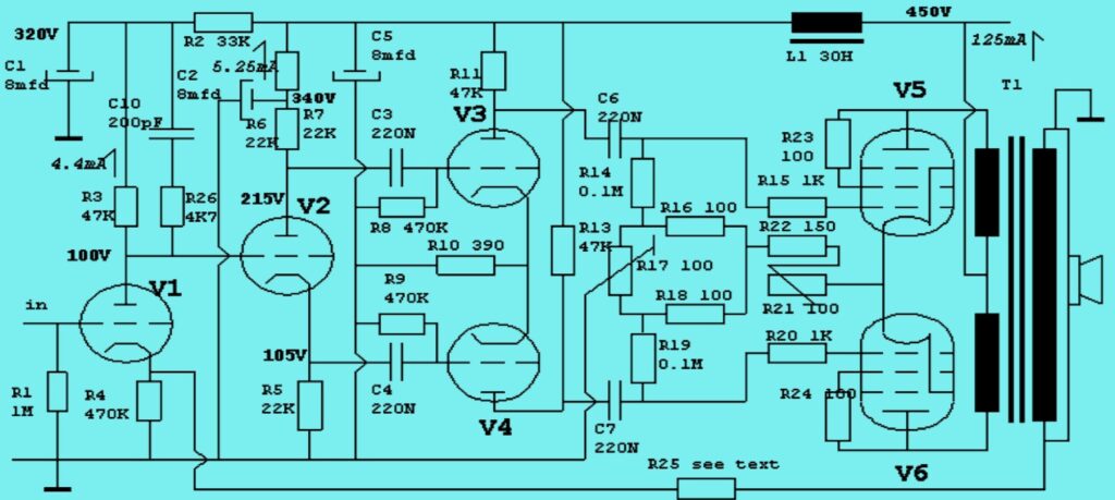
The picture at the top of this page shows the overall circuit of the revised version as published in 1949 in “Wireless World” and indeed it is simple! It consists of three stages, Note that the values of C3 and C4 are the values from the “Ultra Linear Williamson” that was published much later.
The input stage combined with the “concertina” phasesplitter using tubes as 6SN7, 12AU7 or ECC82.
The driver stage. In the original version a 6SN7 was used. For those who are interested in the experiment: 12BH7 and 12AU7 or ECC82 .
The power stage using in the original version a pair of KT66 that was impossible to obtain. Rumors are that it is in the Far East in production again. Alternatively try the latest version of “Sovtek’s” 6L6WXG or 5881 that are capable of handling the dissipation. The slim 6L6GC versions that are in fact 6L6GB wont handle the current! The EL34 or its US counterpart 6CA7 can also be used. American constructors tend to prefer the foreign EL34 and the Europeans vice versa. Currently the Tesla KT77 is available and tried by the author with great succes, leaving the 6L6 versions way behind.
More important then looking at the three individual stages that are quite simple is the fact that those stages together make the amplifier that became famous! Designers took ample efforts to compose an amplifier out of succeeding stages so that the distortion in one stage reduced distortion in the next stage. That is why some circuits became classics! Every change in the circuit can turn a masterpiece into a disaster if you don’t know what you are doing. On paper is exchanging the 6SN7 for the more modern 12AU7 modest surgery. In reality you increase the bandwidth of the phasesplitter because the capacitve load of the 12AU7 on the phasesplitter is only half. This alone can cause instability! The main reason the Williamson amplifier became famous was the output transformer. This was a piece of workmanship that was not seen before. Williamson had calculated that its bandwidth should range straight from 2Hz to 60.000Hz (being the third harmonic of 20.000Hz.)! Only the best transformer possible would allow the amp to operate stable with a strong negative feedback loop. Nowadays it is very common to design amplifiers such that they are straight to 20kHz without feedback.