The amplifier for Pascal Jansen Project
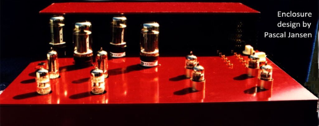
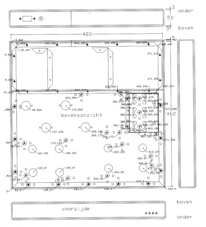
By the end of the nineties while busy developing output transformers for Williamson amplifier a good friend, Pascal Jansen, designer of tone arms for record players showed interest in an integrated tube amplifier with power stages according to the Williamson design. From sketches Autocad drawings were made of the project so the metal parts could be machined automatically. The drawings are shown at the bottom of this page. More information on the design of the output transformers is found in the next chapter, chapter 8.
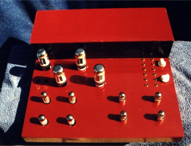
Picture above, the top view of the elegant design, the knobs on the right side are for volume control and input selection, including a phono input, on the left are the loudspeaker outputs. The phono – and the line stage have ECC83 tubes (12AX7), the input stage of the power amp has ECC82 (12AU7), the driver stage 12BH7 and the power tuber are KT77’s .
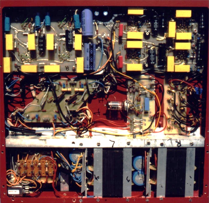
Picture above, the bottom view of the amplifier. The thing is very heavy. Power transformer, main amp and pre-amp have are in separated sections. On top is the single pcb on which the sockets for the noval tubes are mounted as well as most of the components of the amplifier. The square yellow things are the coupling capacitors between the stages. Below the main pcb, left is the pcb on which the power resistors of the power tubes are mounted, in the middle the HT time delay tube (see chapter 9), in the middle on the right side the inputs of the amp. On bottom of the picture, left the power transformer with the fuses and to the right the output transformers, in between the transformers are metal sheets on which the rectifiers and the electrolytic capacitors of the power supply are mounted. Note the orientation of the transformers. This was a good choice.
Later on, every now and then when changing components, the choice for pcb mounting was regretted, the layout had become rigidly set out, and many copper tracks, having insufficient cross section for the current, needed to be beefed up with solder ridges; clearly the old fashioned way with component strips and wired connections would have saved from a lot of extra work.
Bottom view, scan of the amplifier case. Spot welded M5 thread studs for PCB fixation. Note the L shaped metal sheets in the transformer compartment, top of the image
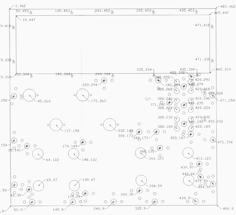
Picture above, scan of the autocad drawing for machining the top aluminium sheet of the amplifier case. It is very questionable if the diskette on which it was saved is still readable.